
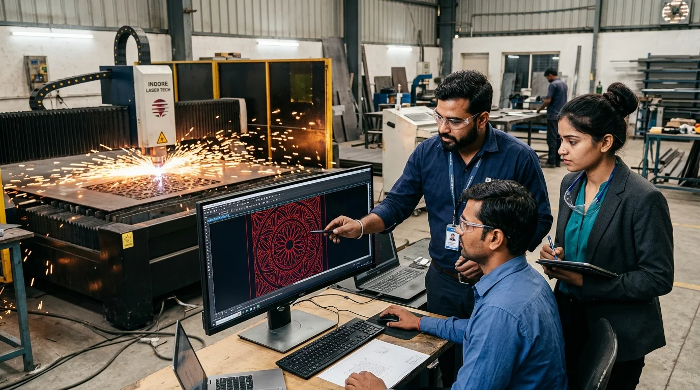
Ask any CNC machine operator in Indore what slows down a job the most, and they won't say thick steel or hard wood. They will say a messy drawing file. Every morning at our Dhar Road workshop, we receive WhatsApp forwards, PDFs exported at odd scales, or CAD files packed with hidden duplicate lines. Preparing a clean dxf file for laser cutting is the single fastest way to cut your machine runtime, avoid burnt edges and get your panels delivered on the same day. Whether you are an architect sending facade sheets, an interior designer ordering a pooja mandir jali, or an engineering student building a prototype through our 2D CNC cutting services, a five minute file check saves hours on the shop floor.
Here is why it matters. A CNC laser or router does not look at a drawing with human eyes. It reads pure geometry. If two lines sit on top of each other, the laser cuts the same path twice, overheating the steel and leaving rough dross. If a corner loop has a tiny 0.2mm gap, the CAM software flags an open contour and refuses to assign inner or outer kerf offset. Worse, if someone draws a 2400mm by 1200mm sheet in inches by mistake, the file opens at 2.4 metres or 60 metres wide.
In this step by step guide, we share the exact file setup rules our CAD engineers use for our CNC metal cutting services in Indore, Acrylic lasers and MDF routers so your file cuts with zero errors on the first pass.
Why CNC Laser Cutters and Routers Need Vector Files (DXF, DWG, CDR) Instead of Images
CNC laser cutters and routers cannot read pixel images like JPG, PNG or WhatsApp screenshots directly. They require mathematical 2D vector paths saved as DXF, DWG, CDR, AI or SVG files that tell the cutting head exact X and Y coordinates to follow.
Homeowners and fabricators often ask why we cannot load a clear Pinterest photo straight into the laser controller. When you zoom in on a JPG or PNG photo, the lines break into blurry grey squares called pixels. A machine head moving at 100 millimetres per second with 0.05mm precision does not know where a blurry grey square starts or ends.
A vector file is built from mathematical formulas connecting start points, end points and arc radii. Whether you scale a vector circle to 10mm or 10 metres, the line stays razor sharp. Industrial CAM programs like CypCut (used on fibre metal lasers), RDWorks (used on CO2 lasers for our acrylic laser cutting service in Indore), and ArtCAM or Vectric Aspire (used for wood and MDF routers) read these vector coordinates and convert them into G-code motion paths. Among all formats, the Drawing Exchange Format, or dxf file for laser cutting, is the universal standard that works across every machine brand on earth.
DXF vs DWG vs CDR vs AI: Which File Format Works Best for Which CNC Machine?
AutoCAD DXF (2004 or R12 version) is the best all-round file for fibre metal lasers and industrial nesting software. CorelDRAW (.CDR) is preferred by Indian sign makers and CO2 acrylic lasers, while DWG and Adobe Illustrator (.AI) work well once converted to clean polylines.
Different design studios use different software. Architects and civil engineers live inside AutoCAD and SolidWorks, while graphic designers and signage shops work in CorelDRAW or Illustrator. Here is how each format behaves on the shop floor:
| File Format | Primary Software | Best CNC Machine Match | Recommended Export Version |
|---|---|---|---|
| .DXF (Drawing Exchange) | AutoCAD, SolidWorks, Rhino, Fusion | Fibre Metal Laser, CNC Router, Plasma | AutoCAD 2004 DXF or R12 DXF (mm) |
| .DWG (AutoCAD Native) | AutoCAD, DraftSight, BricsCAD | Metal Facades, Gate & Railing CAD | AutoCAD 2007 / 2013 DWG (Purged) |
| .CDR (CorelDRAW) | CorelDRAW Graphics Suite | CO2 Acrylic Laser, MDF Jali Router | CorelDRAW Version 17 (X7) or Lower |
| .AI / .EPS / .SVG | Adobe Illustrator, Inkscape | Signage, Logos, Intricate Fretwork | Illustrator CS6 or Exported as DXF |
Step-by-Step: How to Prepare an AutoCAD DXF for Laser Cutting
To prepare an AutoCAD DXF for laser cutting, set units to millimetres at 1:1 scale in Model Space, delete dimensions and title blocks, run EXPLODE on blocks, use OVERKILL to remove duplicate lines, join loops with PEDIT, and save as AutoCAD 2004 DXF.
When preparing an autocad dxf for laser cutting or converting a dwg to dxf for laser cutting, follow this seven step checklist before emailing the file:
- 1. Draw in Model Space at 1:1 Scale in Millimetres: Type
UNITSand set Insertion Scale to Millimetres. Draw an 8x4 foot sheet at 2440 by 1220 units. - 2. Strip Out Non-Cutting Clutter: Delete title blocks, logos, dimension arrows, leader notes, hatch fills and construction lines.
- 3. Move Geometry Near the Origin (0,0): Move the bottom left corner of your parts to coordinates
0,0,0so they open on screen in CypCut. - 4. Flatten Z-Axis Coordinates to Zero: Select everything, type
FLATTENor set Start Z and End Z to0in Properties. - 5. Explode Blocks and Convert Splines: Type
EXPLODEon blocks and Xrefs, and convert splines to polylines withSPLINEDIT. - 6. Run OVERKILL and PEDIT Join: To fix open vectors in autocad, type
OVERKILLto delete duplicate lines, then runPEDIT(Multiple, Join, fuzz distance0.05) so every cutout becomes a closed loop. - 7. Save As AutoCAD 2004 DXF: Use
SAVEASand pick AutoCAD 2004 DXF or R12 DXF for universal compatibility.
Step-by-Step: How to Prepare a CorelDRAW (CDR) File for CNC and Laser Cutting
In CorelDRAW, set page units to millimetres at 1:1 scale, convert all text and shapes to curves (Ctrl+Q), set line thickness to Hairline with no fill colour, weld overlapping shapes, break apart stray nodes, and save as CorelDRAW X7 or export as DXF.
Many interior designers and signage fabricators in Indore send a cdr file for cnc cutting when ordering temple arches, acrylic letters or MDF partitions. To make your coreldraw laser cutting setup trouble free, check these rules:
- Convert All Text to Curves (Ctrl + Q): Select all Hindi or English text and press
Ctrl + Qso letters turn into vector outlines and never get swapped with Arial. - Use Hairline Outline and Zero Fill: Remove all solid fills and set every cut line to
Hairlinewidth. Never convert a thick stroke to an object, or the laser will cut twice. - Weld Overlapping Shapes: Select overlapping petals or script letters and click
Weldso they merge into one continuous outer path. - Avoid Auto-Trace Mess on Low-Res Images: PowerTrace on a blurry screenshot creates thousands of jagged nodes that make the machine stutter. Redraw curves with the Bezier tool instead.
The 5 Golden Engineering Rules: Bridges, Islands, Kerf, Corner Radius and Hole Size
Follow five physical cutting rules: add stencil bridges to floating islands, keep minimum bridge width at 1.5x sheet thickness for metal and 12mm for MDF, leave kerf offset to the CAM operator, round inner router corners, and keep hole diameters larger than sheet thickness.
A file can look fine in AutoCAD and still fail on the machine bed if it ignores the physics of heat and tool bits. Whether you are building a cnc gate design dxf file or a delicate partition, check these five rules during our CNC cutting process review:
1. The Stencil Bridge Rule (No Floating Islands)
Letters like A, B, D, O, P, Q, R and numbers like 0, 4, 6, 8, 9 have closed inner loops. Without bridges, the centre of the letter "O" drops into the scrap tray. Always add 4mm to 8mm stencil text bridges for laser cutting to tie internal islands back to the main sheet.
2. Minimum Bridge Width for Metal vs MDF and Acrylic
Respect the minimum bridge width laser cutting rule for your material. On metal sheets (MS, SS 304, Aluminium), keep every metal web at least 1.5 times the sheet thickness (4mm to 6mm on gates and railings). On 12mm to 18mm boards cut via our CNC cutting MDF services in Indore, keep bridges at least 12mm to 15mm wide so the router bit does not snap the strip.
3. Understanding Laser Cutting Kerf Width
A fibre metal laser or CO2 acrylic laser has a laser cutting kerf width of 0.1mm to 0.3mm, whereas a CNC router uses a 3mm, 4mm or 6mm carbide bit. Do not manually offset your drawing for kerf unless designing press-fit joints; our CAM software offsets toolpaths automatically.
4. Inside Corner Radius on CNC Routers vs Lasers
A 0.15mm laser beam cuts sharp 90 degree inside corners effortlessly. A CNC router uses a round spinning bit (a 6mm bit leaves a 3mm inside radius). If two wood parts must slot together flat, add dog-bone corner fillets in your vector file for cnc router.
5. Minimum Hole Diameter vs Sheet Thickness
On a fibre laser, never draw a hole smaller than the steel sheet thickness (minimum 4mm hole on a 4mm MS plate) to prevent molten slag blowback.
Layer and Colour Coding Standard for Cut, Engrave and Etch Lines
Use standardised RGB colours on separate CAD layers so the machine operator knows which lines to cut through and which to engrave: Black or White for outer perimeter cuts, Red for inner cutout holes, Blue for surface vector marking, and Green for sheet reference frames.
When a drawing contains both through-cuts and surface etching, use this four layer convention:
- Layer 1 (Red / RGB 255,0,0) for Inner Cutouts: All internal jali holes and slots that must be cut first while the main sheet is held steady.
- Layer 2 (Black / White) for Outer Perimeter Cut: The final outside boundary cut that releases the part from the 8x4 foot sheet.
- Layer 3 (Blue / RGB 0,0,255) for Vector Scoring and Etching: Low power laser marking lines for fold guides, text outlines or decorative grooves.
- Layer 4 (Green / RGB 0,255,0) for Non-Cutting Reference Lines: Notes, grain direction arrows or CNC press brake bend lines.
How File Cleanliness Directly Lowers Your CNC Cutting Cost in Indore
A clean DXF file with minimal nodes, zero duplicate lines and smart sheet nesting reduces laser pierces and cutting time by 15 to 30 percent, directly lowering your per square foot cutting bill and eliminating material waste on 8x4 foot sheets.
Many people don't realise that a messy CAD file costs real money. As we explain in our CNC cutting price in Indore guide, laser and router job work is priced by machine runtime, pierce count and sheet utilisation. When a traced vector has 8,000 jagged nodes instead of 200 smooth arc segments, the CNC controller decelerates at every node, doubling the machine minutes. When you nest your parts inside a standard 2440mm by 1220mm (8x4 foot) boundary with a 10mm outer margin and 5mm part spacing, you get maximum yield from every sheet. Architects planning large multi-sheet projects can also check our guide on CNC cutting panels for architects in Indore for full sheet sizing standards.
Conclusion
Taking five minutes to prepare a clean dxf file for laser cutting is the secret to crisp edges, exact part tolerances and faster turnaround times. Set your drawing units to millimetres at a 1:1 scale, purge duplicate lines with OVERKILL, join open vectors into closed polylines, check your bridge widths and save as AutoCAD 2004 DXF or CorelDRAW X7. And if you don't know AutoCAD or CorelDRAW, don't worry. Just bring your hand sketch, reference photo or site measurements to our team at Gurunanak Timber Market, Dhar Road, or contact Eish CNC Designs on WhatsApp to get your CAD vector file and cutting quote ready within 24 hours.
Frequently Asked Questions
-
Which DXF version is best for CNC laser cutting machines?
Save your drawing as AutoCAD 2004 DXF or AutoCAD R12/LT2 DXF in millimetres (mm) at a 1:1 scale. Newer DXF formats often store complex spline blocks that industrial CAM software like CypCut or ArtCAM can misread.
-
Why can't a CNC laser cutter read a JPG, PNG or WhatsApp image directly?
A JPG or PNG is made of coloured pixels, whereas a CNC laser cutter or router needs mathematical X and Y vector coordinates to move the cutting head. Pixel images must be traced or redrawn into closed vector polylines in AutoCAD or CorelDRAW.
-
What is the minimum bridge width for laser cutting metal and MDF jali?
For metal laser cutting, keep every bridge at least 1.5 times the sheet thickness (6mm bridge on a 4mm MS sheet) so heat does not warp the strip. For MDF and HDHMR CNC router cutting, keep bridges at least 12mm to 15mm wide.
-
How do you fix overlapping lines and open vectors in AutoCAD before exporting a DXF?
Select your entire drawing, run the EXPLODE command on blocks, type OVERKILL to delete duplicate overlapping segments, and run PEDIT with the Join option (fuzz distance 0.05mm) to close all open loops into continuous polylines.
-
Do I need to add kerf offset inside my DXF file for laser cutting?
No. Draw your parts at their exact finished dimensions at a 1:1 scale. Our CAM operator applies inner and outer kerf compensation automatically in CypCut or ArtCAM based on the laser nozzle or router bit diameter.
-
What if I only have a hand sketch or Pinterest photo and no DXF file?
You can send your photo or rough measurements to Eish CNC Designs in Indore on WhatsApp. Our in-house CAD team converts sketches into clean, production ready DXF and CDR files and shares a preview before cutting.